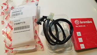
Ducati GT1000 Front Brake Microswitch Replacement
Three long weeks ago, I did the usual check of the lights, turn signals, etc. on my 2007 Ducati GT1000 when I noticed a) my brake light was pretty bright and b) is seemed a little flaky as I squeezed the brake lever, as in ‘on-off-on’ instead of the expected, ‘on’ when I squeezed the lever and ‘off’ when I wasn’t. The bike being 14 years old and not having ridden it in a few weeks, I just figured it needed some persuasion. Squeezed it a dozen times, it started working as advertised, and then I went out for a ride.
When I got home, I noticed it was bright again, which made realize I was a little stupid and unsafe for assuming it would just work itself out. From there, I went to the Ducati of Omaha site, my go-to for parts, pulled up the drawing and ordered… the wrong thing. At this point I also realized there wasn’t really anything on the internet that talked about this, so I figured I’d share my story and hopefully save you a little time and headache.
The (incorrect) switch in the parts list is:
|
53940211A - FRONT BRAKE LIGHT SWITCH × 1 |
It was in stock and got to me within a few days, but it’s the wrong switch! Two male connectors on the end, but they would need to be soldered/spliced into the plug on my bike. This part looked just like the one on the parts list, and was consistent (consistently wrong) from 2007 to 2010. I know I could make it work, but I thought it was unlikely that this was how Ducati expected this part to be replaced. I sent the dealer a photo of what my switch looked like and we worked together to find the correct part number:
|
53940541A - FRONT BRAKE LIGHT SWITCH × 1 |
Naturally, it cost about twice as much, wasn’t in stock, had to come from Italy, etc., but at least I was on my way. When it finally got here, I set aside a couple of hours and got down to business. This is one of the easiest jobs I’ve done on this bike and once you do it once, the second time through would probably take 10 minutes, depending on how anal you are about cable dressing:
1. Unplug the old switch where it’s zip-tied to the chassis. The good news is you don’t have to take the tank off to access this. I did that my first time through, but it wasn’t necessary.
2. Test the new switch prior to installation. No point in twisting, turning, and routing if something’s wrong with the part! Plug in the new switch, turn the bike to the ‘On’ position, and press the plunger on the microswitch. When it’s not pressed, the brake light should be on. When you press the button, the light should go off. Turn the key back to the ‘off’ position. Now that we’ve confirmed the switch is working, time to install and route the new cable.
3. Press the brake lever to get room to work, and gently pry the old microswitch off by moving it to the right (as viewed from the front of the bike). Let it dangle and clean the 14 years of dirt and bugs that may have gotten behind it.
4. Press the brake lever again, and gently press the new switch into the holes in the same mounting point where the old switch was installed.
5. The next step is not an exact science, but I looked at the tension, sag, etc. of the cables between each tie wrap and took a few photos for reference. Then, starting from the closest zip-tie to the microswitch, snip the old zip tie, get the old microswitch cable out of the way, and place the new cable in the same spot. Loosely zip tie, then move on to the next zip tie and repeat. Don’t tighten the zip ties yet, because you may need to make some adjustments once you have the cable fully replaced.
6. Run the cable down the handlebar, tie off to the trellis frame, and route to the female plug on the bike. Plug in the cable.
7. Turn the key back to the ‘on’ position and make sure everything’s working by pressing and releasing the brake lever to confirm the light is lighting up as expected. Turn the handlebar from lock-to-lock and make sure there’s no excessive tension, stretching or binding of the cables. Pull the brake lever at a few different points and make sure there are no switch issues or intermittent faults.
8. Once satisfied that everything’s working and fits well, tighten all zip ties and trim off the excess.
9. Hoon around for a bit and enjoy the fact the people behind you now know when you’re stopping.
This is definitely not rocket science and the only tools needed are a small flat screwdriver and a pair of wire cutters. Good luck!


Comments
Post a Comment